today I want to talk a little bit about what I imagined for the lighting of the build. This is going to be very interesting.
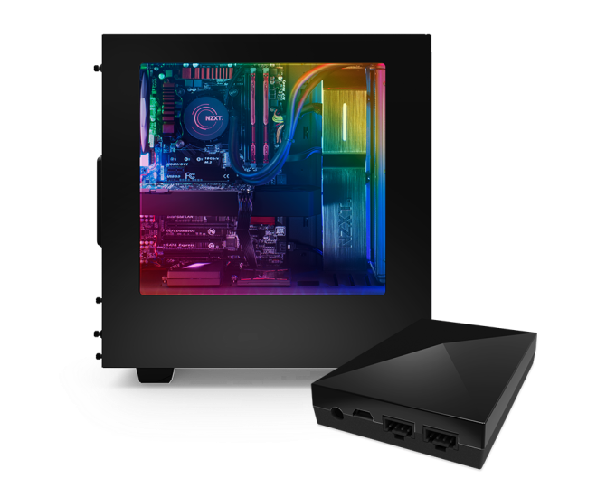
As you might know RGB Lighting is getting more and more popular and there are tons of gadgets out there that provide great features and good looks. My build will have a fully RGB back-lid housing and the acrylic sheets underneath the components as well. Yesterday I was looking for some great solutions and came across this one here:
It has awesome lighting features and I think the colors blend perfectly, it is easy to install and exactly what I thought would be great for my build.
Furthermore I have decided to cut out the logos of the companies that “provided” the components and use colored single LEDs to illuminate them in their specific color.
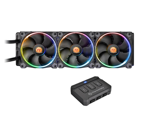
To make the colors even more vivid my radiator fans will have Thermaltake Riing 12 RGB fans on them. They have “only” 256 color variations but I think the difference is negligible. Have a look here:
today I want to share with you my plans for the GPU setup of this build. This one is kind of special because it will be the most expensive and most important part of the build.
My plans for the GPUs are to mount them facing up from the wooden board, which means that I need those beloved PCIe riser cables/cards. I know there is a lot of controversy out there and I want to share with you what I have found out so far:
1. PCIe risers in general do not effect performance!
Let me clarify this a bit. PCIe risers in general do nothing more than extend the length of the interconnect between PCIe slot and graphics card. What matters though, and this is very important, is that they need to be shielded by default. It can work that you buy cheap unshielded ones and wrap them in aluminium foil BUT there is absolutely no guarantee and btw it looks like crap. Take the extra money and invest in shielded ones from a renown manufacturer like 3M. But keep in mind: The longer your cable gets the higher the chances of EMI interrupting your signal gets even with high quality cables.
2. The cross-sectional area matters.
I have read a forum post of a guy who claimed that when a GPU is put under load, it pulls power from the PCIe slot as well, which I can understand. He said, that when the cross-sectional area increases, conductance decreases and that you want to look for cables with lower AWG (American Wire Gauge) rating. I found out that 3M cables have an AWG rating of 30. When searching for riser cables I came across a company that is located in Taiwan called Li-Heat. They claim their wires have an AWG 28, are shielded and can transfer PCIe signals over long distances. Proof can be found here although I personally don’t believe everything I see.
My build will feature the 2nd best of the 4 upcoming Pascals which will presumably be called GTX 1080. Depending on the price and performance per card, how they will scale and what new features they will have, I will either just get 1 and leave space for a second one later on or they are kicking ass and I will be buying two of them at once. Of course this also depends on the price of the i7 6850K when launched.
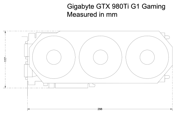
So now the post is getting too long and I’ll leave for today. I made and AutoCAD drawing of the Gigabyte GTX 980 Ti G1 Gaming which will be used as a placeholder for the 1080s in my future plans. But have a look yourself: Gigabyte GTX 980Ti G1 Gaming (PNG), Gigabyte GTX 980Ti G1 Gaming (DWG).
So I have started a new thread on the LinusTechTips forum where I will plan and log the process of this build. See here: €5000 wall-mounted PC
4 days ago I started creating the first AutoCAD 2016 drawings for the millimeter measured ATX mainboard standard. I want to remind you that I just started learning AutoCAD and that my drawings may look a bit newbish to the professional eye but that was not the point of making the drawing.
To be able to mount the mainboard correctly onto the acrylic sheet and the wooden mounting plate, you need to know exactly where the holes are located and how far they are apart. If you are using inches etc. you could refer to this specifications-sheet: ATX Standard If you use the non-retarded version of measuring (just kidding all systems are beautiful) then please feel free to use this: ATX Standard (PNG), ATX Standard (DWG)
ATX Specification in mm
I hope this will make it simpler for you and me during the building process. I will use this to let the people that will cut and drill the acrylic for me know, how they have to do it, but I hope that I will find somebody who can lend me his equipment because I think cutting the acrylic myself will make the build more personal.
Hi guys, this is Steve. I’m a currently 17 yo male student from Bavaria, Germany finishing 12th grade and preparing for my (hopefully) CS studies at the Technische Universität München.
When I got my first computer running Windows 95, I would sit there for hours drawing pixel by pixel in Paint. Since then many years have passed, where I got to know my best friend who showed me the world of gaming. Since then many years have passed, where I got to know my best friend who showed me the world of gaming. Starting with simple Online-Games and later becoming a full stack gamer, I needed a more powerful machine than my Dell Inspiron 530. My father and I decided to build a complete system by ourselves, besides our lack of expertise in this topic. So we threw some components together and built a €1,400 gaming monster with the latest hardware of that time. This was the igniting spark of my passion about the depths of PC hardware configuration and assembly.
Since then I have configured, built and optimised many many systems theoretically and in practice for myself and a few friends, which were all air cooled, non-overclocking systems in regular PC cases. Now that my interests have shifted a lot and the only time I am gaming is during some weekends and the holidays, I am planning for something that fits my needs better. The new setup will mainly be used for my studies and the diverse hobbies in 3D-rendering, parallel computing, image and video manipulation and (sometimes) gaming I have.
Initial thoughts
First I was thinking about buying an iMac 5K with 4GB M395X GPU and Quad-Core i7 4GHz processor. The €3,500 price-tag didn’t surprise me all too much and since I knew I would want 2 more displays, the decision to build a custom Windows PC fell even faster. So I started thinking about what I wanted to do and thought that a really kick-in-the-butt understatement system with absolute no noise emission would be really cool. 6-Core i7 5930K, dual Gigabyte GTX 980 Ti G1 Gaming, Fractal Define R4 case (no window) and ASUS X99-M WS would make a great Mini PC to take to LAN-Partys. As soon as I finished tinkering, I proposed the idea to my parents. Of course my mother didn’t understand anything and to my surprise my father wasn’t convinced either. He thought that when we built my first PC I went with the most fierce looking setup with tons of LEDs etc. and now I would prefer an entirely closed PC that is matte black?! “No,” he said, “I’ve got a better idea. How about building your own custom case or even better, mount that PC on the wall with all components visible!” For me that sounded like a terrible idea at first and slightly disappointed I went upstairs. After a few days though, the idea sounded like the most bad-ass thing I could imagine and I wanted to build it.
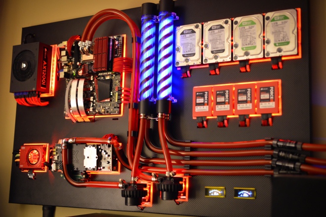
Once again I sat down and started googling: ‘wall mounted PC’ and found this beast of a machine.
MAXXPlanck V2X by Show4Pro (overclock.net)
I was mesmerized by the sheer beauty and cleanness of the build. The way he mounted the components on acrylic sheets with the lighting in the back, the water cooling and the carbon fibre backplate. I really like the red appearance although I’m a bit tired of it because 80% of people are using that color-scheme. But at the time this build started I think it was very one-of-a-kind.
My build will feature the latest technological ‘inventions’ of these days in the custom PC product range, which to me means acrylic tubing and RGB lighting.
Intention of this blog
I started this blog because I think the ultra-custom PC-Build “Elite” is not dropping enough information on how to plan and realize such a build. At least in my case I didn’t have any idea on how to get the acrylic to light up correctly, what LEDs to use and the (in my opinion) most mysterious of them all: HOW THE F*** DO YOU MOUNT THESE GRAPHICS CARDS?!Furthermore I found out that there is really only ONE single half-way comprehensible technical drawing of an ATX motherboard and the corresponding mounting holes and that is measured in inches which is this here: ATX Mainboard
To make it a little bit easier for me and future builders, I decided to create an AutoCAD version of all of the components I’ll be using. They will be measured in millimeters and hosted on a public dropbox I’ll launch soon with screenshots of them as well.
I hope you will enjoy following this blog and I promise, the next posts will be a lot shorter!